Jump to:
TMR is not a new idea in the world of ASIC design. It was published as far back as 1962 in the IBM Journal of Research and Development. However, it has become an essential design solution for ASIC chips sent into space, a vast environment filled with radiation.
Most overviews of TMR within ASIC design are described at a high level. This discussion will center on a more detailed approach for integrating TMR within a physical design methodology using the Cadence Design Systems Innovus Tool.
What Is Triple Modular Redundancy and How Does It Work?
Electronic systems operating in a radioactive environment, such as outside the Earth’s atmosphere, will eventually encounter malfunctions. These malfunctions are due to the high energy particles from radiation passing through the circuit transistors.
This energy can alter the transistor’s performance, which can cause the circuit to shift voltage levels. The upset voltage shifts can affect data being processed and look like noise, while state machines could be upset and completely malfunction. The integrity of data values — whether for control, microcode, or measured data — becomes suspect.
TMR techniques can mitigate these system upsets. System changes will require additional logical structures and physical implementation techniques to prevent the radiation from altering the design function.
The Effects of Radiation on Electronic Systems
Radiation is energy or matter that moves through space. It can occur as electromagnetic or particle radiation. Radiation is classified into two categories — ionizing radiation and non-ionizing radiation. When ionizing radiation encounters materials such as semiconductor circuits, it can knock electrons out of the semiconductor’s atomic orbits and change the circuits’ operating properties.
Electromagnetic radiation is the transfer of energy from massless photon particles moving at the speed of light. It is assessed in the frequency spectrum. The higher the frequency, the higher the energy presented by the radiation. Electromagnetic radiation in the ultraviolet, X-ray, and gamma-ray spectrums poses the highest damage risk to semiconductors.
Particle radiation comprises fast-moving subatomic particles that have intrinsic mass, such as protons, electrons, and nuclei of atoms. The speed these particles travel can be at any magnitude up to almost the speed of light. These particles have great penetrating power, making shielding a challenge.
Radiation can impact electronic systems either as a Single Event Effect (SEE) or as a Cumulative Event Effect (CEE).
CEE and SEE Design Solutions
Total dose accumulation is a “cumulative event” radiation effect that causes operational parametric changes to the transistors. A minor effect is transistor failure through degraded timing or inability to switch. By using larger and hardened layout architectures of the transistor, the digital cell functions’ endurance can extend the silicon’s life cycle. The IP vendor provides the mitigation of cumulative radiation effects using radiation-hardened cell layout and design structures.
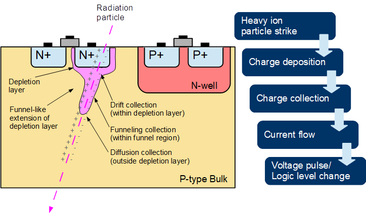
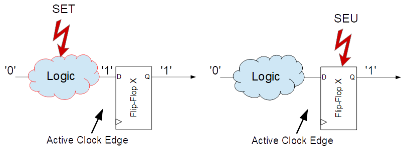
“Single-event” high-energy particles can affect logic by momentarily changing the state. This change is known as a Single Event Transient (SET). The high-energy particles can flip the output state of a register, known as a Single Event Upset (SEU). This electrical disturbance caused by the high-energy events will create functional errors in the system.
Figure 1. SEEs are caused by a single radiation particle strike
Figure 2. SEE’s Transient and Upset Events
As shown in Figure 2, the SET originates from the logic feeding the flip–flop. When the high-energy event occurs at the same time as the active edge of the flip-flop, the flip-flop will capture the incorrect state. An SEU occurs when the high–energy event strikes the flip-flop at the same time the clock active edge occurs. The flip-flop’s internal circuit will be upset, and the wrong state will be captured. High-energy events can be filtered or ignored with a modification of the design.
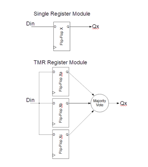
The single flip-flop can be replaced with three flip-flops whose outputs pass through the majority voting circuit to ignore a single flip-flop bit flip — this is called TMR.
Even though the redundant nature of a TMR structure is designed to be fault-tolerant, a SET glitch on the input of the TMR can be captured with the clock edge and produce multiple-bit errors in the TMR. To counter this possibility, the input must be delayed to each TMR flip-flop, or the clock must arrive at the TMR flip-flops at skewed delays to prevent this glitch from being captured with multiple flip-flops in the TMR. This way, only one flip-flop in the TMR will catch the flipped state from the SET glitch. The majority voting circuit will resolve the correct state.
A high-energy event could upset more than one flip-flop with an SEU if all three TMR flip-flops are closely placed together. A solution to this issue is maintaining minimum spacing for each TMR flip-flop, spreading out the TMR module and reducing the probability multiple TMR flip-flops are impacted by the SEU.
Several solutions can reduce the effects of radiation on electronic designs. This discussion focuses only on implementing TMR.
TMR Implementation
TMR is a fault-tolerant strategy that substitutes a single flip-flop with three flip-flops. The triplet flip-flop outputs are logically evaluated to resolve the correct result by majority voting. The TMR filters out single-flipped register values due to an SEU or SET.
For example, in RTL, the following logic without TMR can be transformed with TMR techniques by creating a custom TMR module, which instantiates the triple redundancy and voting logic.
Synthesized code flip-flop call:
DFF_X1 u1 (.Q(q1), .CLK(clk), .D(d1));
DFF_X1 u2 (.Q(q2), .CLK(clk), .D(d2));
DFF_X1 u3 (.Q(q3), .CLK(clk), .D(d3));
DFF_X1 u4 (.Q(q4), .CLK(clk), .D(d4));
Change all flip-flop calls to TMR module call:
TMRDFF u1 (.Q(q1), .CLK(clk), .D(d1));
TMRDFF u2 (.Q(q2), .CLK(clk), .D(d2));
TMRDFF u3 (.Q(q3), .CLK(clk), .D(d3));
TMRDFF u4 (.Q(q4), .CLK(clk), .D(d4));

module TMRDFF (Q, CLK, D);
output Q;
input CLK;
input D;
wire qa, qb, qc;

RH_DFF TMR_A (.Q(qa), .CLK(CLK), .D(D));
RH_DFF TMR_B (.Q(qb), .CLK(CLK), .D(D));
RH_DFF TMR_C (.Q(qc), .CLK(CLK), .D(D));
AO222_X1 TMR_Q (.Z(Q), .A1(qa), .A2(qb), .B1(qa), .B2(qc), .C1(qb), .C2(qc));
endmodule //TMRDFF
note: RH_DFF is the radiation-hardened cell provided by the IP vendor.
TMR Implementation Concerns
Incoming SETs can be avoided by adding a staggered delay on the D input or phasing the clock arrival timing to each TMR register. As previously mentioned, the triplet’s flip-flop placement is critical to avoid multiple flip-flop upsets. After gate-level synthesis, TMR is inserted into the design by replacing each flip-flop call with a TMR-flip-flop module call. If the technology library has a “radiation-hardened” flip-flop, use this cell to improve total dosage tolerance.
The placement procedure must identify each flip-flop of the TMR instances. The placement of TMR flip-flops — TMR_A, TMR_B, and TMR_C — requires minimum spacing to keep them spread apart to avoid multiple register upsets during a single event.
During synthesis, clock constraints can be set to create staggered phase differences, further mitigating upsetting events.
create_clock -name "CLK"  -period $CLK_PER [get_ports {CLK}]
set_clock_latency     2.0     [get_clocks {CLK}]
set_clock_latency     2.0     [get_pins */TMR_A]
set_clock_latency     3.0     [get_pins */TMR_B]
set_clock_latency     4.0     [get_pins */TMR_C]
TMR must be implemented in the design netlist before the physical implementation can begin. Physical separation of the TMR flip-flops is critical to this mitigation strategy’s success. Use an instance naming convention to identify the members of a flip-flop triplet. Next, consider the physical design approach utilizing Cadence’s Innovus Physical Design Tool.
A Cadence Physical Design Approach for Implementing TMR
The Innovus Cadence Physical Design Tool accommodates TMR functionality and checking through instance space groups, which are supported within the cell placement engine. Instance space groups allow the spacing of predefined instances, including registers and flip-flops used for TMR. The following TCL script illustrates a TMR solution in Innovus.
Start by building a dictionary of all the TMR cell groups using the instance naming convention determined earlier. Once the groupings are identified, a space group is created for the cells in each group, and spacing distances are set between group members in the X and Y directions. Finally, placement is run, honoring the created instance space groups.
As an additional feature, include error checking to ensure each group contains three members and visual highlighting to help identify the triplet group members.
Note: This script uses Legacy Innovus commands, not the Stylus language equivalents.
####################################
# Create TMR Instance Space Groups #
####################################
proc create_tmr_space_groups { } {

   set design_name my_design

   ###################################################################################
   # TMR instance spacing constraints within TMR triplet group
   # These spacing values are arbitrary. There is no “one size fits all”.
   #            Determine values that fit your design requirements
   ###################################################################################
   set tmr_inst_spacing_x 30.000
   set tmr_inst_spacing_y 10.000

   ####################################################################
   # Create dictionary for organizing all TMR triplet instance groups #
   ####################################################################
   set tmr_info [dict create]

   set tmr_pattern "^.+_\[abc\]_reg\|xc_rcv_\[abc\]_i\|ts_\[abc\]_i.*$"
   set all_tmr_inst_list [lsort -dictionary [dbget -e -regexp top.insts.name $tmr_pattern]]

   ##############################
   # If TMR instances exist.... #
   ##############################
   if { [llength $all_tmr_inst_list] > 0 } {

       ############################################################
       # Organize all TMR triplet instance groups into dictionary #
       ############################################################
       foreach tmr_inst $all_tmr_inst_list {
           if { [regexp {(^(.+)(_[abc]_reg|xc_rcv_[abc]_i|ts_[abc]_i)(.*)$)} $tmr_inst -> match
           tmr_prefix tmr_bit tmr_suffix] } {
               dict lappend tmr_info ${tmr_prefix}_${tmr_suffix} $match
           }
       }

       set color 49
       set x 1
       set error_count 0

       foreach { tmr_info_key tmr_triplet_list } [dict get $tmr_info] {

           if {[llength $tmr_triplet_list] != 3} {
               Puts "ERROR - TMR group found with not exactly 3 instances:  $tmr_triplet_list"
               incr error_count
               continue
           }

           ##########################################################
           # IMPORTANT -> TMR instances must have a "placed" status #
           ##########################################################
           setInstancePlacementStatus -name $tmr_triplet_list -status placed

           #########################################################################
           # Delete possible pre-existsing TMR Instance Space Group with same name #
           #########################################################################
           delete_inst_space_group ${design_name}_tmr_triplet_inst_group_($x)

           ##########################################################
           # Create a TMR Instance Space Group for each TMR triplet #
           ##########################################################
           create_inst_space_group ${design_name}_tmr_triplet_inst_group_($x) -inst
           $tmr_triplet_list -spacing_x $tmr_inst_spacing_x -spacing_y $tmr_inst_spacing_y
           –checking_box cross_only

           incr x

           ##################################################################
           # Highlight/Color each TMR triplet group to easily identify them #
           ##################################################################
           if {$color > 64} {
               set color 49
           }

           foreach tmr_inst $tmr_triplet_list {
               highlight [dbget -p1 top.insts.name $tmr_inst] -index $color
           }
           incr color
       }

       #########################
       # Create the TMR report #
       #########################
       set report_filename "TMR_inst_space_group.rpt"
       report_inst_space_group -file $report_filename

       #############
       # Messaging #
       #############
       if {$error_count > 0} {
           Puts "ERROR - Found $error_count groups with not exactly 3 instances. These were
           skipped."
       }

       Puts "Found and created [expr $x - 1] TMR instance space groups."
       Puts "Report File: $report_filename"

       #####################################################################################
       # IMPORTANT -> setPlaceMode variable MUST be set to true for Placement to honor TMR #
       #              Instance Space Group constraints                                     #
       #####################################################################################
       setPlaceMode -check_inst_space_group true
   }

   return
}
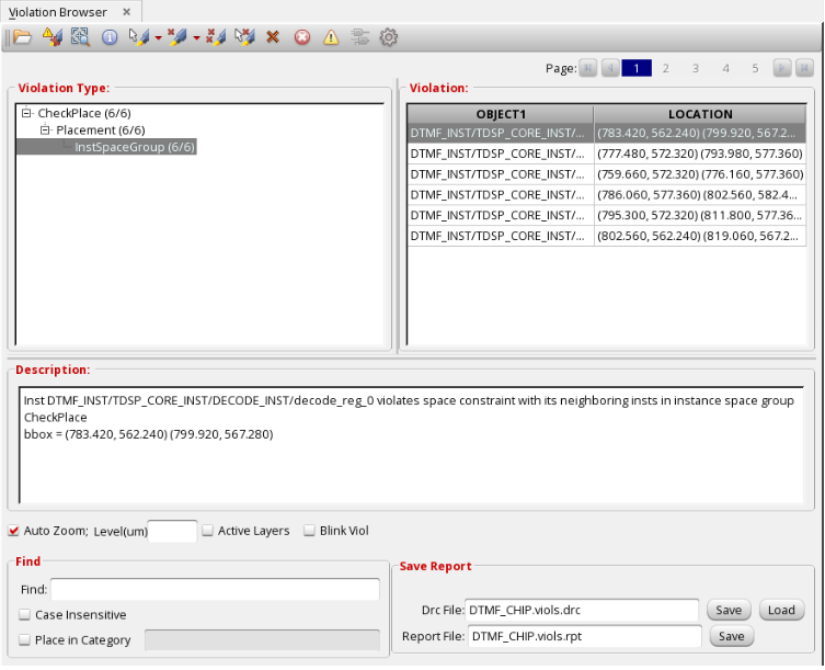
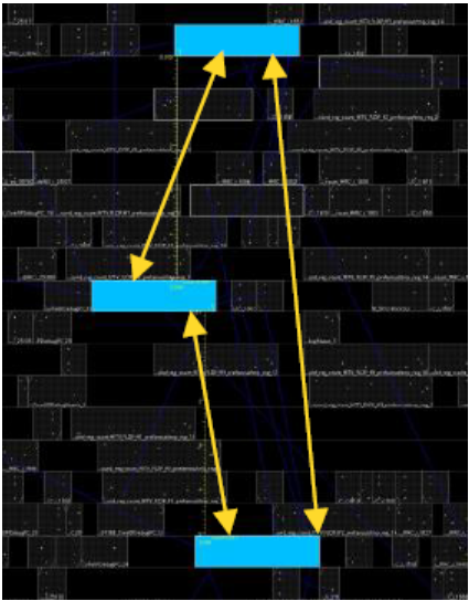
After the placement phase, the triplets can be spaced according to the preset spacing rules. The checkPlace function will also report any groups with incorrect placement in the Violation Browser.
 |
 |
Overhead of Mitigation With TMR
Using TMR for all registers will increase the size and power over four times. Because the flip-flops must be spread apart to ensure an SEU won’t upset more than one flip-flop, routing density increases greatly. The maximum operating
clock frequency is also reduced due to the added delay caused by the majority voting logic and clock skewing.
Additional Mitigation Techniques
Minimizing the number of TMR circuits will reduce the area impact. State machines should include TMR due to the functional impact of a bit flip. Additionally, the state machine must be designed to have no undefined states. However, the data path impacts of bit flips may not be as severe as a crash. Using filters or error correction codes (ECCs) could take up less area and power. Memories should also use ECCs.
Solve RAD Hard ASIC Design Challenges With ASIC North
Radiation effects can degrade and potentially kill electronic circuits. Even if there is no physical damage, an SEU or SET can render an electronic piece of equipment inoperable.
While TMR does represent some overhead in area, power, and maximum operating clock frequency, it does mitigate functional failures of circuits in space-based applications. In conjunction with proper group placement — as demonstrated using the Innovus place and route tool — the effectiveness of the TMR technique can be maintained through the design cycle.
ASIC North brings digital, analog, radio, sensors, and security together to provide a single integrated custom silicon chip solution tailored to your needs. Contact us today for a free development quote from your mixed-signal design partner.


